College of Liberal Arts & Sciences
5C10.20 - Sliding Capacitors

Code Number:
References:
5C10.20
Demo Title:
Sliding Capacitors
Condition:
Good
Principle:
Capacitance Dependence on, Distance Between Plates
Area of Study:
Electricity & Magnetism
Equipment:
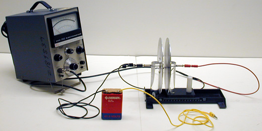
Sliding capacitors, Keithley Electrometer, Overhead DC voltmeter, 67.5 V battery, Dielectric plates, Sliding Capacitors, and Electroscope.
Procedure:
Video Credit: Jonathan M. Sullivan-Wood
Set the voltmeter to the 100 volt range. Assemble the apparatus as shown. Touch the positive battery cable to the positive plate and the meter voltage should read around 70 volts. Move the plates together and the voltage will drop to around 30 volts.
Another twist on this is to place the plates close together first and then charge them. Now, pull them apart and the voltage will rise.
Use the dielectrics as desired or a thick textbook will also act as a dielectric. The Plexiglas dielectric may have to be cleaned with alcohol to remove any built up static charge.
- Taehum Jang, Hyejin Ha, Sang Ho Sohn, Jungmin Moon, "Measurement of the Electric Fields in Parallel Plate Capacitors", TPT, Vol. 62, #5, May 2024, p. 392.
- Marcos Alfredo Salami, Joao Bernardes da Rocha Filho, Claudio Galli, "Capacitors Made by Drawing with Graphite on Paper or Plastic", TPT, Vol. 45, # 6, Sept. 2007, p. 392.
- Mustafa Baser, "Hydraulic Capacitor Analogy", TPT, Vol. 45, # 3, March 2007, p. 172.
- Nathaniel R. Greene, "Energy Flow for a Variable-Gap Capacitor", TPT, Vol. 43, # 6, p. 340, Sept. 2005.
- Walter Connolly, "Measuring Capacitance and the Dielectric Constant", TPT, Vol. 26, # 3, p. 169, March 1988.
- John B. Kwasnoski, "Measuring the Charge Stored on a Capacitor", TPT, Vol. 25, # 8, Nov. 1987, p. 492.
- Thomas B. Greenslade, Jr., Richard H. Howe, "A Modern Use of Volta's Electroscope", TPT, Vol. 19, # 9, Dec. 1981, p. 614.
- Herbert H. Gottlieb, "Variable Capacitor", TPT, Vol. 5, # 2, Feb. 1967, p. 86.
- G. W. Parker, "Electric Field Outside a Parallel Plate Capacitor", AJP, Vol. 70, # 5, May 2002, p. 502.
- Ali Naini and Mark Green, "Fringing Fields in a Parallel-Plate Capacitor", AJP, Vol. 45, # 9, Sept. 1977, p. 877.
- Ching Yao Fong and C. Kittel, "Induced Charge on Capacitor Plates", AJP, Vol. 35, # 11, Nov. 1967, p. 1091.
- Ed-1, 2: Freier and Anderson, A Demonstration Handbook for Physics.
- R. W. Pohl, "The Mechanism of the Decay of the Field", Physical Principles of Electricity and Magnetism, p 30.
- David Kutliroff, "83, Investigating the Properties of a Capacitor", 101 Classroom Demonstrations and Experiment For Teaching Physics, p. 184.
- Borislaw Bilash II, David Maiullo, "Pie Plate Capacitor", A Demo a Day: A Year of Physics Demonstrations, p. 258.
- "The Parallel Plate Capacitor", Johns Hopkins University, March 2002.
- Jearl Walker, "5.16, A Gurney Fire", The Flying Circus of Physics Ed. 2, p. 225.
- W. Bolton, "14. The Parallel Plate Capacitor", Book 4 - Electricity, Physics Experiments and Projects, 1968, p. 29 - 30.
- W. Bolton, "13. Capacitance", Book 4 - Electricity, Physics Experiments and Projects, 1968, p. 27 - 28.
Disclaimer: These demonstrations are provided only for illustrative use by persons affiliated with The University of Iowa and only under the direction of a trained instructor or physicist. The University of Iowa is not responsible for demonstrations performed by those using their own equipment or who choose to use this reference material for their own purpose. The demonstrations included here are within the public domain and can be found in materials contained in libraries, bookstores, and through electronic sources. Performing all or any portion of any of these demonstrations, with or without revisions not depicted here entails inherent risks. These risks include, without limitation, bodily injury (and possibly death), including risks to health that may be temporary or permanent and that may exacerbate a pre-existing medical condition; and property loss or damage. Anyone performing any part of these demonstrations, even with revisions, knowingly and voluntarily assumes all risks associated with them.