College of Liberal Arts & Sciences
5C30.42 - Capacitive Impedance Demo

Code Number:
References:
5C30.42
Demo Title:
Capacitive Impedance Demo
Condition:
Good
Principle:
Parallel vs. Series Capacitance
Area of Study:
Electricity & Magnetism
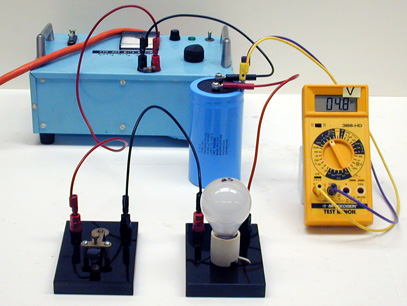
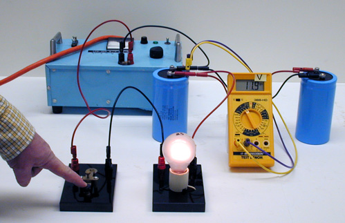
Equipment:
150 V DC power supply, Capacitors (2), Light bulb (25 watt), Key switch, Digital or Overhead Volt Meter, Resistor, Knife Switch.
Procedure:
Hook the power supply, capacitor, light bulb, and Key switch in series as a circuit. Observe the voltages with and without the capacitor in the circuit.
You can also add a second capacitor in parallel which doubles the time for charging. As the voltage goes up on the meter the light will become dimmer.
CAUTION: Do not go above 75 VDC on the power supply when adding the second capacitor.
The other part of the demo shown is the same as above except that a resistor replaces the light bulb.
The two circuits may also be placed in parallel as shown.
Another meter may be substituted for the overhead volt meter.
- Baswajit Ray, "When Is a Capcitor NOT a Capacitor?", TPT, Vol. 44, # 2, Feb. 2006, p. 106.
- Sudha Krishnan, Monoranjan Rao, "Hydrostatic Analogy for the Two-Capacitor Problem", AJP, Vol. 50, # 7, July 1982, p. 662.
- En-4: Freier and Anderson, A Demonstration Handbook for Physics.
- Ronald Newburgh, "Two Theorems on Dissipative Energy Losses in Capacitor Systems", Physics Education, Vol. 40 # 4, July 2005, p. 370.
- W. Bolton, "Capacitor in a d.c. Circuit", Book 4 - Electricity, Physics Experiments and Projects, 1968, p. 33.
Disclaimer: These demonstrations are provided only for illustrative use by persons affiliated with The University of Iowa and only under the direction of a trained instructor or physicist. The University of Iowa is not responsible for demonstrations performed by those using their own equipment or who choose to use this reference material for their own purpose. The demonstrations included here are within the public domain and can be found in materials contained in libraries, bookstores, and through electronic sources. Performing all or any portion of any of these demonstrations, with or without revisions not depicted here entails inherent risks. These risks include, without limitation, bodily injury (and possibly death), including risks to health that may be temporary or permanent and that may exacerbate a pre-existing medical condition; and property loss or damage. Anyone performing any part of these demonstrations, even with revisions, knowingly and voluntarily assumes all risks associated with them.