College of Liberal Arts & Sciences
5L20.13 - L-R, R-C, Phase Shift Demo


Code Number:
References:
5L20.13
Demo Title:
L-R, R-C, Phase Shift Demo
Condition:
Good
Principle:
L-R-C Phase Shifts in a Circuit
Area of Study:
Electricity and Magnetism
Equipment:
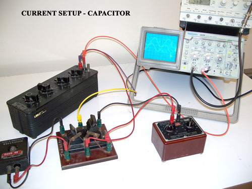
500 mh Standard Inductor, Decade Inductor, Resistor Box, Decade Capacitor Unit, Double Throw Knife Switch, Wave Generator (Wavetek), Oscilloscope.
Procedure:
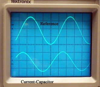
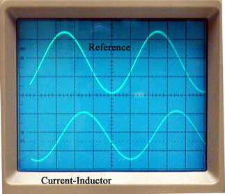
Images 1, 2, 3, and 4
If you want to show that the capacitor and inductor are 90 degrees out of phase you will need to measure the current across the resistor. Our apparatus will not be exact but will come close to being 90 degrees out of phase. Since we are measuring current here the capacitor signal will lead the reference signal and the inductor signal will lag the reference signal.
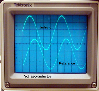
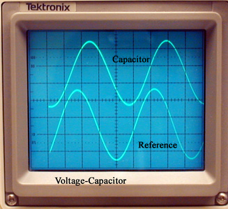
Images 5, 6, and 7
Arrange the circuit as shown with the capacitor on one side of the switch and the inductor on the other side. Set the wave generator to the sine wave function. Measure across the resistor to get the reference trace. Move the knife switch and observe the phase shift as the capacitor is added into the circuit. Move the switch to the other poles and observe the shift as the inductor is added into the circuit. The shifts will be about the same but in opposite directions in relationship to the reference trace. Since we are measuring voltage here the capacitor signal will lag behind the reference signal and the inductor signal will lead the reference signal.
NOTE: Only one ground wire is needed for both channels of the oscilloscope.
- Jim Oliver, "Observing Voltage Phases in RC, RL, and RLC Circuits", TPT Vol. 35, # 1, Jan. 1997, p. 30.
- Thomas A. Walkiewicz and James R. Kirk, "Characteristic Curves", TPT, Vol. 32, # 2, Feb. 1994, p. 90.
- Ronald Ebert and James Harvey, "RLC Phase Measurement", TPT, Vol. 30, # 3, Mar. 1992, p. 135.
- Robert A. Egler and William M. Mauney, "Capacitor Current-Voltage Phase Difference", TPT, Vol. 29, # 6, p. 398, September 1991.
- Everett Hinton, "RLC Phases", TPT, Vol. 29, # 9, Dec. 1991, p. 550.
- L. Ribaud and P.G. Mattocks, "The Octopus and the Phasor", TPT, Vol. 28, # 3, p. 160, March 1990.
- Forrest P. Clay, Jr., "Demonstration of Phase Relationships in a Series RLC Circuit Using a Four-Channel Miltiplexer and a Single-Channel Oscilloscope", AJP, Vol. 47, #4, April 1979, p. 337.
- Zdenek Hurych, "Study of the Phase Relationships in Resonant RCL Circuits Using a Dual-Trace Oscilloscope", AJP, Vol. 43, #11, Nov. 1975, p. 1011.
- En - 2: Freier and Anderson, A Demonstration Handbook for Physics.
- "Simple Alternating-Current Series Circuit", Selective Experiments in Physics, CENCO, 1962.
- "Alternating-Current Series Circuit", Selective Experiments in Physics, CENCO, 1962.
- W. Bolton, "Phase Difference", Book 4 - Electricity, Physics Experiments and Projects, 1968, p. 62-63.
Disclaimer: These demonstrations are provided only for illustrative use by persons affiliated with The University of Iowa and only under the direction of a trained instructor or physicist. The University of Iowa is not responsible for demonstrations performed by those using their own equipment or who choose to use this reference material for their own purpose. The demonstrations included here are within the public domain and can be found in materials contained in libraries, bookstores, and through electronic sources. Performing all or any portion of any of these demonstrations, with or without revisions not depicted here entails inherent risks. These risks include, without limitation, bodily injury (and possibly death), including risks to health that may be temporary or permanent and that may exacerbate a pre-existing medical condition; and property loss or damage. Anyone performing any part of these demonstrations, even with revisions, knowingly and voluntarily assumes all risks associated with them.