College of Liberal Arts & Sciences
5L30.25 - DC vs. AC Voltages and the Meaning of Root Mean Square
Code Number:
References:
5L30.25
Demo Title:
DC vs. AC Voltages and the Meaning of Root Mean Square
Condition:
Good
Principle:
Root Mean Square
Area of Study:
Electricity & Magnetism
Equipment:
12 volt bulb, 0 - 20 v, 8 amp. power supply, 24 volt transformer, 6 Volt Battery, Variable Pot., Oscilloscope, Variac, DC Power Supply, Light Bulbs, Isolation Transformer, Multimeters (Keithley) (2).
Procedure:
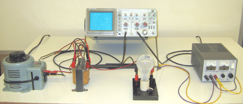
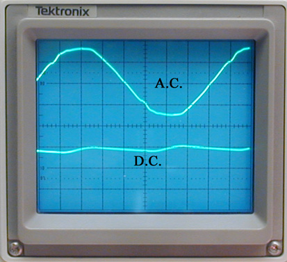
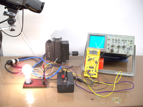
Arrange the apparatus so the the oscilloscope is monitoring the AC or DC current. Attach the light bulb to the AC current and observe the trace on the oscilloscope. Then unhook the bulb from the AC and hook onto the DC leads and again observe the trace. The AC trace will show the usual sine wave as the voltage is increased while the DC will show a straight horizontal line which moves upward on the oscilloscope as the voltage is increased.
NOTE: Make sure you use the center tap on the 24 volt transformer so you don't accidentally burn out the 12 volt bulb.
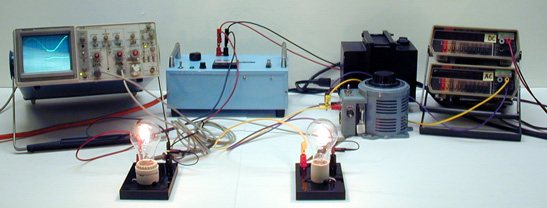
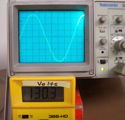
Set the demo up as shown. Turn the voltage of the AC and DC power supplies to the same voltage as observed by the light bulbs and as read on the meters. Measure the voltages with the oscilloscope and see that the AC voltage is actually larger when measured peak to peak than the observed RMS measured voltage.
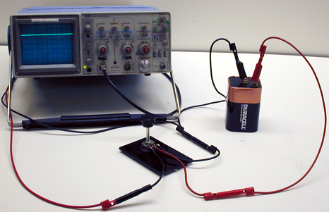
The demonstration in picture 3 is used to show that DC voltage gives a straight line and not a sine wave. Turn the variable pot and observe how the trace moves on the scope.
- Patrik Vogt, Stefan Kuchemann, Jochen Kuhn, "The Flashing Light Bulb: A Quantitative Introduction to the Theory of Alternating Current", TPT, Vol. 59, #2, Feb. 2021, p. 138.
- Donald S. Ainslie, "Showing the Ratio of Ac Peak", TPT, Vol. 19, # 8, Nov. 1981, p. 551.
- Yaakov Kraftmakher, "1.14 Electric Power in AC Circuits", Experiments and Demonstrations in Physics, ISBN 981-256-602-3, p. 54.
- Curt Suplee, "Electricity in motion", Everyday Science Explained, National Geographic, p. 90.
- W. Bolton, "Alternating Current and Meters", Book 4 - Electricity, Physics Experiments and Projects, 1968, p. 55-56.
Disclaimer: These demonstrations are provided only for illustrative use by persons affiliated with The University of Iowa and only under the direction of a trained instructor or physicist. The University of Iowa is not responsible for demonstrations performed by those using their own equipment or who choose to use this reference material for their own purpose. The demonstrations included here are within the public domain and can be found in materials contained in libraries, bookstores, and through electronic sources. Performing all or any portion of any of these demonstrations, with or without revisions not depicted here entails inherent risks. These risks include, without limitation, bodily injury (and possibly death), including risks to health that may be temporary or permanent and that may exacerbate a pre-existing medical condition; and property loss or damage. Anyone performing any part of these demonstrations, even with revisions, knowingly and voluntarily assumes all risks associated with them.