|
|
|
|
|
|
|
|
|
Code Number: 5L20.21
Demo Title: Resonance Circuits
Condition: Good
Principle: Parallel/Series AC Resonance
Area of Study: Electricity & Magnetism
Equipment:
Oscilloscope, Wave Generator (Wavetek), Overhead Circuit Diagram, Resonance Demo, Variac, Decade Capacitance Unit, Inductor Coil, Iron Cores, Amp Meter, Light bulb, decade inductor, 80 watt amplifier, 6 volt light bulb.
Procedure:
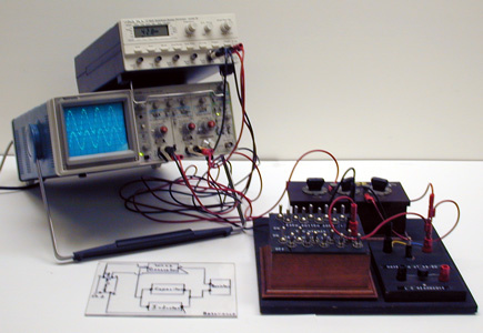
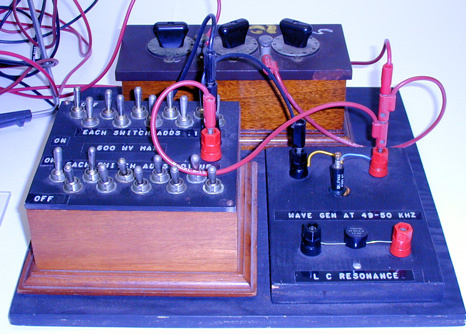
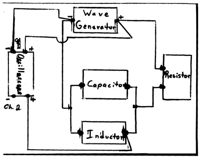
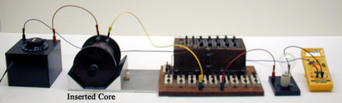
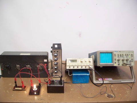
Connect the labeled leads to the proper inputs of the oscilloscope and the wave generator. Set the wave generator to the 1 to 100 KHz range. As you sweep the generator through the range you will see a point of maximum resonance on the oscilloscope. The reference trace on the scope is the direct generator input. Screw the core into the small inductor and notice how the resonant peak shifts. By sweeping the frequencies again you can find the new resonant frequency. You may also change the capacitor values if desired.
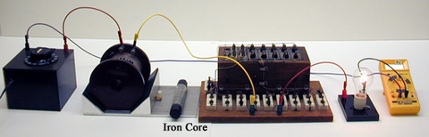
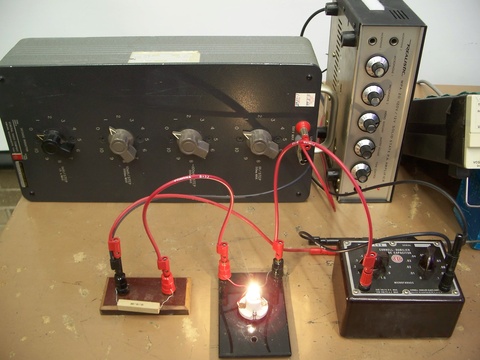
Assemble the circuit with the Variac, capacitor, inductor, and light all in series. With the proper capacitance value (this is set at 25 mfd at present) the circuit will go in and out of resonance as you insert and remove the iron core in the inductor coil. The light bulb is used as a visual indicator of this phenomenon. Usually for this demo the capacitor is set for 25 mfd which will mean that the light will come on when you turn the Variac up and will go out when you insert the core. NOTE the caution for the following variation: You will need to remove the 4 screws in the capacitor top case to so it can be removed so you can reset the capacitor to a different value. Be sure you have the circuit turned off or unplugged as all the exposed wires in the capacitor bank will be at 125 Volts otherwise. You can also set the capacitor at 6 mfd, and when you turn the Variac up the light bulb will glow dimly. As you insert the iron core the light gets brighter, and as you continue to insert the core you go past resonance and the light once again becomes dim.
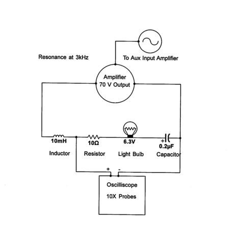
You may use a 6 volt light bulb as an indicator of circuit resonance if desired. Put the wave generator, capacitor, inductor, and amplifier all in series. The speaker output of the amplifier is connected to the 6 volt bulb. Sweep the frequency between 0 and 10 kHz. and observe the resonance.
References:
- Fabiana Botelho Kneubil, "Driven Series RLC Circuit and Resonance: A Graphic Approach to Energy", TPT, Vol. 58, #4, April 2020, p. 256.
- Yaakov Kraftmakher, "Two Demonstrations with a New Data-Acquisition System", TPT, Vol. 52, #3, Mar. 2014, p. 164.
- Philip Backman, Chester Murley, and P. J. Williams, "The Driven RLC Circuit Experiment", TPT, Vol. 37, # 7, p. 424, Oct. 1999.
- Se-yuen Mak, "Qualitative Demonstrations of Parallel/Series Resonance", TPT, Vol. 37, #3, Mar 1999, p. 179.
- S. Y. Mak and P. K. Tao, "Measurement of Self-Inductance", TPT, Vol. 26, #6, Sept. 1988, p. 378.
- Jim Oliver, "Observing Voltage Phases in RC, RL, and RLC Circuits", TPT, Vol. 35, #1, Jan. 1997, p. 30.
- Russell Akridge, "AC Reactance Without Calculus", TPT, , Vol. 35, #1, Jan. 1997, p. 20.
- Zenon Gubanski, "Damped Oscillations", TPT, Vol. 7, #1, Jan. 1969, p. 59.
- David D. Lockhart, "Effect of Variable Frequencies on Reactive Circuits", TPT, Vol. 7, #1, Jan. 1969, p. 59.
- Pierre Cafarelli et al, "The RLC System: An Invaluable Test Bench for Students", AJP, Vol. 80, #9, Sep. 2012, p. 789.
- Michael C. Faleski, "Transient Behavior of the Driven RLC Circuit", AJP, Vol. 74, #5, May 2006, p. 429.
- Zdenek Hurych, "Study of the Phase Relationships in Resonant RCL Circuits Using A Dual-Trace Oscilloscope", AJP, Vol. 43, #11, Nov. 1975, p. 1011.
- Keung L. Luke, "Laboartory Investigation of Free and Driven Oscillations Using A RLC Circuit", AJP, Vol. 43, #7, July 1975, p. 610.trical Circuits. II. Tuned Coupled Circuits", AJP, Vol. 29, #4, Apr. 1961, p. 251.
- Edward J. Burge, "Definitions of Resonance and Exact Conditions for Resonace in Some Elec
- Edward J. Burge, "Definitions of Resonance and Exact Conditions for Resonace in Some Electrical Circuits. I. Definitions of Resonance for Series and Parallel LCR Circuits", AJP, Vol. 29, #1, Jan. 1961, p. 19.
- W. A. Hilton, "Resonance Experiment", Apparatus Notes, July 1965-December 1972, p. 56.
- Freier and Anderson, "En-1, Eo-15", A Demonstration Handbook for Physics.
- Richard Manliffe Sutton, "A-26", Demonstration Experiments in Physics.
- Richard Berg, Rich Baum, K7-27 - RLC Circuit Demonstration, June 1999, plus included circuit diagram.
- "Basic Direct Current Measurements", Lab Experiment, Johns Hopkins University, 2005.
- Yaakov Kraftmakher, "3.2. LCR Circuit", Experiments and Demonstrations in Physics, ISBN 981-256-602-3, p. 149.
- Robert L. Wild, "LRC Circuit", Low-Cost Physics Demonstrations, # 148, p. 87.
- "Simple Alternating-Current Series Circuit", Selective Experiments in Physics, CENCO, 1962.
- "Alternating-Current Series Circuit", Selective Experiments in Physics, CENCO, 1962.
- "Kirchhoff's Laws", Selective Experiments in Physics, CENCO, 1962.
- W. Bolton, "36. Voltage Magnification With A Resonant Circuit", Book 4 - Electricity, Physics Experiments and Projects, 1968, p. 69 - 70.
- W. Bolton, "33. Electrical Resonance", Book 4 - Electricity, Physics Experiments and Projects, 1968, p. 64.
- W. Bolton, "30. Alternating Current Applied to a Resistor, A Capacitor and an Inductor", Book 4 - Electricity, Physics Experiments and Projects, 1968, p. 57 - 58.
- W. Bolton, "6. Electrical Circuit Energy Level", Book 3 - Atomic Physics, Physics Experiments and Projects, 1968, p. 20 - 21.