|
|
|
|
|
|
| 
|
| 
|
| 
|
|
Code Number: 6Q20.10
Demo Title: Abbe's Theory of Imaging - Optical Fourier Transform
Procedure:
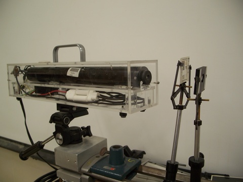
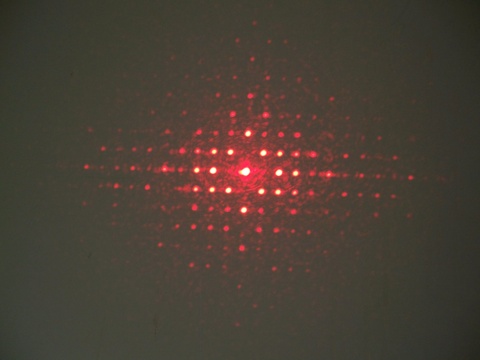
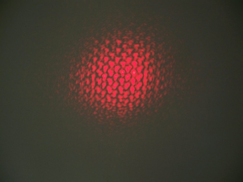
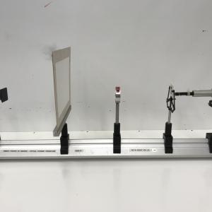
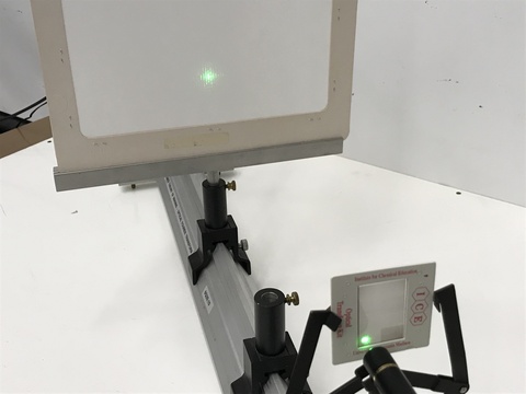
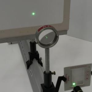
Demo 1 - Get the "Unit" slide from the "Electron Diffraction - Optical Simulation" demo (6D20.58). The bottom left hand pattern of small characters is the one to use. This will give a crystal diffraction pattern when a laser beam is pointed though the slide. Place an 18 mm lens from the Michelson Interferometer (6D40.10) demo in front of the slide and observe that the diffraction pattern is now transformed to the real image of the optical crystal showing the original "L" shaped characters. Basically you see the diffraction pattern consisting of the body factor convolved with the form factor. When you insert the lens you see its Fourier transform, the real image of the Optical Crystal.
Demo 2 - This setup is that described in "Optics", 4th Ed. by Eugene Hecht, p. 524, figure 11.5 in "The Lens as a Fourier Transformer" section. It is essentially the same as the above setup. The difference is that the transparency slide is placed at the focal length of the lens on one side, and the screen is placed at the focal length of the lens on the other side. The camera looks at the image on the screen without and with the lens in place. In this case the image on the screen with the lens in place looks like the image without the lens, only smaller. The bottom left hand pattern of the "VSEPR" slide from the 6D20.58 "Electron Diffraction - Optical Simulation" demo is used in this setup.
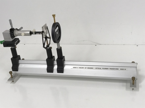
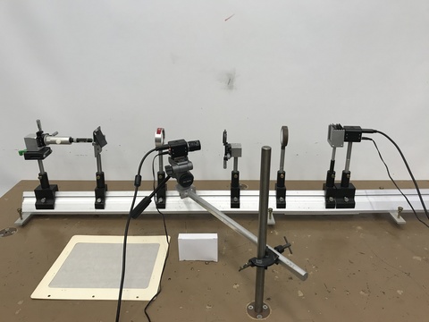
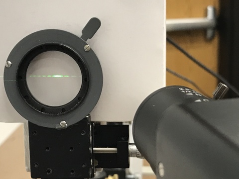
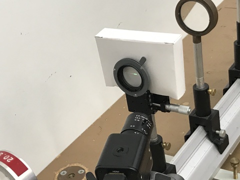
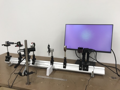
Demo 3 - This demonstration is described in "Optics", 4th Ed. by Eugene Hecht, p. 612, figure 13.31. Our version of the demonstration uses a single slit instead of the letter "E" in the book but is otherwise the same. Note that all the demo components are fixed at the focal lengths of the lenses. The single slit diffraction pattern can be seen at the iris position. Using a second camera external to the optics rail, you can show the diffraction pattern by either closing the iris or by putting a cardboard screen behind or over the iris as shown in the pictures. The camera on the optics rail after all the Fourier transforms will show an image of the single slit which will dim and become less focused as the iris is closed.
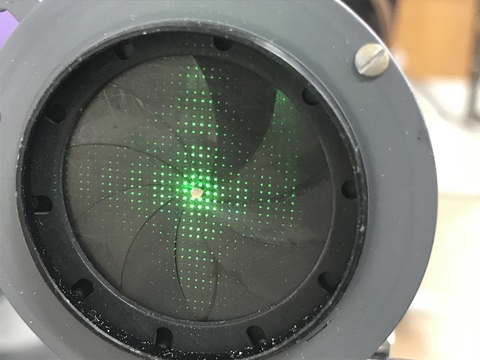
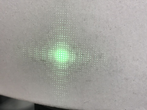
Demo 4 - Note that this is the same demo as Demo 3 except we replace the single slit with a fine mesh screen. This demonstration is described in "Optics", 4th Ed. by Eugene Hecht, p. 612, figure 13.31. Our version of the demonstration uses a fine mesh screen instead of the letter "E" in the book but is otherwise the same. Note that all the demo components are fixed at the focal lengths of the lenses. The fine mesh screen diffraction pattern can be seen at the iris position. Using a second camera external to the optics rail, you can show the diffraction pattern by either closing the iris or by putting a cardboard screen behind or over the iris as shown in the pictures. The camera on the optics rail after all the Fourier transforms will show an image of the fine mesh screen which will dim and become less focused as the iris is closed.
References:
- J. Nicholas Porter, David J. Anderson, Julio Escobedo, David D. Allred, Nathan D. Powers, Richard L. Sandberg, "Coherent Diffraction Imaging in the Undergraduate Laboratory", AJP, Vol. 93, #5, May 2025, p. 415.
- Jack Higbie, "Abbe's Sine Theorem from a Thermodynamic and Fourier Transform Argument", AJP, Vol. 49, #8, Aug. 1981, p. 788.
- Bernard M. Jaffe, "Geometrical Optics Derivation of the Fourier Transform Property of a Lens", AJP, Vol. 48, #2, Feb. 1980, p. 157.
- D. G. Sargood, "On Abbe's Theory of Imaging: A Simple Lecture Room Demonstration", AJP, Vol. 46, #2, Feb. 1978, p. 185.
- Dieter B. Ast, "Optical Simulation of the Origin of Contrast in the Electron Microscope", AJP, Vol. 39, #10, Oct. 1971, p. 1164.
- Anthony Gerrard, "An Elementary Theoretical Approach to the Abbe Theory of Optical Image Formation", AJP, Vol. 31, #9, Sept. 1963, p. 723.
- Katarina Kranjc, "Simple Demonstration Experiments in the Abbe Theory of Image Formation", AJP, Vol. 30, #5, May. 1962, p. 342.
- G. L. Rogers, "The Abbe Theory of Microscopic Vision and the Gibbs Phenomenon", AJP, Vol. 22, #6, Sep. 1954, p. 384.