Code Number: 8A20.45
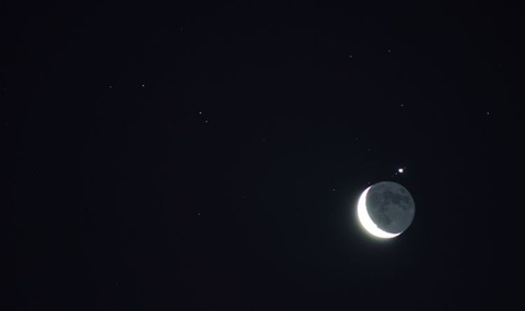
Demo Title: Occultation
Condition: Good
Principle: Occultation
Area of Study: Astronomy
Equipment:
Saturn Videotape, now on digital media.
References:
- Kenneth J. Adney, "Racing with the Moon", TPT, Vol. 30, # 5, May 1992, p. 292.
- Doug Cunningham, John Hlynialuk, "Grazing Occultations", TPT, Vol. 21, # 4, April 1983, p. 218.
- Francis X. Hart, J. Steve Massey, "Determination of a Planet's Diameter by Occultation Time - An Introductory Astronomy Exercise", AJP, Vol. 45, # 10, Oct. 1977, p. 914.